Die Casting in the next decade holds the promise of MORE for the die caster… More exacting parts and processes… More demanding customers… More shortage of skilled Die Casting and Process Engineers… and Worldwide more insistence on improved quality and greater profitability.
The Visi-Trak mission statement is to supply ongoing innovation designed to “Advance the Die Casting Process and Increase Customer’s Profits”. This represents well over forty years of continuous innovation and improvements to process in the industry. Improving process improves not only product quality; but improves profits for the die caster.
Visi-Trak Sensors, Monitors, Controls as well as software solutions, meet present and ongoing industry demands. The focus has been on design of products and system that provide the most accurate picture of the very dynamic die casting process. Our products, installed worldwide, are focused on accuracy, but also have proven ability to survive long term in the demanding die casting environment. All the elements of our systems (Fig. 1) were designed to meet the unique process demands of die casting. These system elements outlined in Figure 2 can be installed on new machines or retrofit in “Building Block” fashion to any machine. These various functions provide a uniform data collection and analysis format that can be installed on any of your machines at affordable prices to monitor your entire operations and using common data specifications and analytics regardless of the machine models to be monitored.

Fig. 2
Plantwide Building Blocks:
- Precision Linear Sensor Technology and High-Speed Data Acquisition: Visi-Trak® Sensors and FasTrak 2 & 3 Data Collection Cards.
- Process Monitoring – Data visualization, Diagnostic and complete machine and PLC Monitoring Software. True-Trak 20/20™ Monitoring and Analysis Systems.
- Shot Control – High performance Olmsted throttling valves with Woodward HRT, Direct-Drive throttling valves. SureTrak2™
- Advanced PLC visualization, Diagnostic, and Set-up Software for complete cell integration. Includes Traceability hardware and software integration. And plant wide quality control distribution and monitoring. TotalTrak™
- Integrated Plant Management with distributed networking to shop office and Back Office of all data archived for data analytics and analysis. Visi-Trak 360
Visi-Trak® Sensors & FasTrak2™ Data Collection
The first of the building blocks for process automation consists of the Visi-Trak® sensor assembly and the FasTrak2™ Data Collection and Control cards. This is the foundation for all Visi-Trak systems. They provide the vital feedback signal for both monitoring and control systems. Accuracy and ability to survive on continuous production basis are paramount. The assembly consists of a target shot cylinder piston rod or follower tail rod that has been modified by machining helical grooves, evenly spaced, along its length. The grooves are over plated with chrome and then ground to an even surface with original O.D. dimensions. The result is a smooth, polished rod that presents a regularly varying magnetic response. The encapsulated transducer detects variation in the magnetic field caused by the rod’s grooved internal structure – at speeds up to 480 IPS or 12 MPS at .0125” position resolution. The Visi-Trak transducer which is housed in an encapsulated, stainless steel housing in close proximity to the rod that generates signals that follow the helical groove profile which provide equal incremental changes of position that require no calibration since it is incorporated in the precision machined groove. (See figure 3 – How does the sensor work)

Fig. 3
The Visi-Trak sensor calculates position by counting pulses generated as the rod strokes past the encapsulated transducer. Velocity is determined by calculating the time interval of each pulse transition through a full helical pitch – Velocity = to Distance (known and pre-calibrated in rod helical grooves) divided by the time interval between each pulse transition. This is achieved by running a precision 33 MHz Timer on the high speed FasTrak2™ Data Collection Board to time pulse intervals. (This is shown in Figure 4) Alternative groove profiles of 20 pitch, 2 mm pitch or 1 mm pitch can be incorporated in the shot cylinder piston rod (The preferred embodiment) or mounted as a follower tail rod which is pulled in parallel with the main piston rod. (See Figure 5)

Fig. 4

Fig. 5
After completion of the slow phase, where metal ladled into the sleeve is advanced at slow speed (usually less than 20IPS) until it reaches the sleeve full position P-1 and runner full position P2, the shot is accelerated at high speed (up to 480 IPS) to begin the very dynamic filling phase of the shot. It is imperative during this highly dynamic phase that the sensor selected can maintain true velocity vs. position reference as the metal is forced thru the gates on the die especially if closed loop shot control is being employed. After the cavity fill is complete the signal rod decelerates rapidly as the rod either hits home or with control is automatically decelerated to achieve flashless low impact control. The monitoring at this phase of the shot cycle transitions to the need to track intensification vs. time and intensification squeeze distance vs. time, a much slower event in terms of velocity. This is an extremely important measure of the effectiveness of the intensification and is best measured as a plot of position change vs. time.
Position Based Sampling:
To determine velocity Visi-Trak uses the FasTrak2™ Board precision clock to time the pulse intervals from the transducer as shown in Figure 4. The FPGA on the FasTrak Board provides all the position-based timing data in real time during the shot and transmits this data to the shot monitoring system where the velocity vs position profile is plotted for visualization. This technique optimizes the velocity calculation which is the main area of interest for analyzing machine and process issues and failures. The real advantage of this technology is that as the rod moves faster the faster calculated velocity values are updated. Whereas with time based data (typically calculated by taking time slices on a 1 to 3 millisecond basis) the data gets further and further apart the faster the rod travels. (See plot from competitors system plotting velocity vs. time.)

Fig. 6
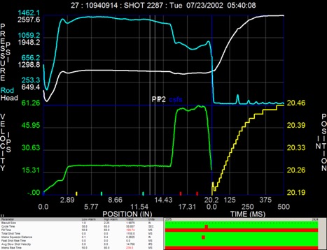
Figure 6 shows a shot taken for illustration of the advantages of position-based sampling. This profile shows a plot of Head & Rod pressure vs. position and a plot of shot velocity vs. position. This profile had a slow shot distance of 13.7” and total time of 949 msec.; a fast shot time of 55 msec. and total distance of 6.64”. Referring back to Fig. 4 it shows a table comparing shot stroke Displacement (change of position); Time in milliseconds, Time based samples with 3 msec. sample interval for 1000 data points vs. position-based samples of same event. The main takeaway here is in the comparison of the number of samples taken using the two alternative data acquisition techniques. In the slow phase the time-based samples provided 316 updates while the Position Based samples provided 1040 updates. In the fast shot there were only 18 updates using the time-based method and over 532 updates with the position-based technique. This comparison would be further exacerbated at higher speeds.
Visi-Trak optimizes the parameter being monitored by dynamically switching from position-based sampling for slow and fast shot to time-based sampling for intensification pressure vs. time and Intensification Squeeze vs. time to measure plunger penetration vs. time usually using a one msec. sample interval. To optimize the appropriate view the FasTrak board populates four different quadrants with different X axis values shown in four different quadrants. The upper left quadrant plots Head & Rod pressure vs. position (during filling). The lower left quadrant plots Velocity for slow and fast shot vs. position. The upper right quadrant plots intensification pressure vs. time and intensification change of position vs. time to measure plunger squeeze. (Fig. 7)

Fig. 7
Not all monitoring methods are created equal. Using the right sampling method at the right time gives the most complete picture while relying on time-based sampling alone almost guarantees you will miss out on the most important information. It’s like having a photo finish that is taken once a second versus one that is taken based on the cars position in relation to the finish line. (Fig. 8)

Fig. 8
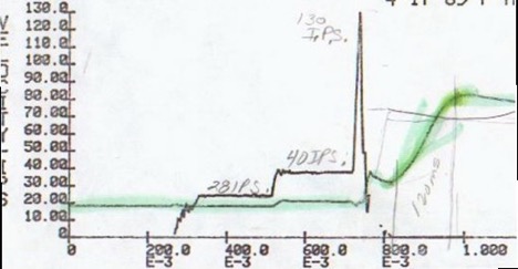
As you can see in this time-based only plot generated by another monitoring solution the system loses precision during the most critical phases of the shot. This entire fast shot phase is reduced to three data points. (Fig. 9)

Fig. 9
Position based sampling provides the most accurate calculation of the shot during the dynamic filling phase without necessity for any calculations. In addition, position-based sampling is the only way you can use a shot overlay function to compare directly the last shot overlay over an earlier reference shot profile to see how a shot is repeating. (Fig. 10)

Fig. 10
Comparing Position Sensing Technologies:
In general, linear position sensing is a broadly applicable technology in the industrial setting. Hundreds of vendors offer solutions based on a dozen or so core technologies including potentiometers, magneto resistance sensors (hall effect, GMR) LVDT and inductive as well as magnetostrictive (Temposonics, Baluff). In extreme environments some of these technologies are not suitable for linear position sensing. Potentiometers are not generally appropriate for high speed sensing because of mechanical coupling and wear. Capacitive sensors have a narrow range of travel and narrow operating temperature range as do optical devices. LVDT’s are not generally suitable for long stroke applications.
Types of sensors
- String/Cable actuated potentiometers – supply proportional analog signals proportional to shot stroke and velocity. Not suitable for continuous production usage due to mechanical coupling which results in false feedback results due to sudden acceleration to high speed as well as whipping on sudden impact at cavity fill.
- Cable actuated encoders – again subject to mechanical whip during high speed accelerations and decelerations provides inaccurate shot data. Not suitable for continuous production monitoring.
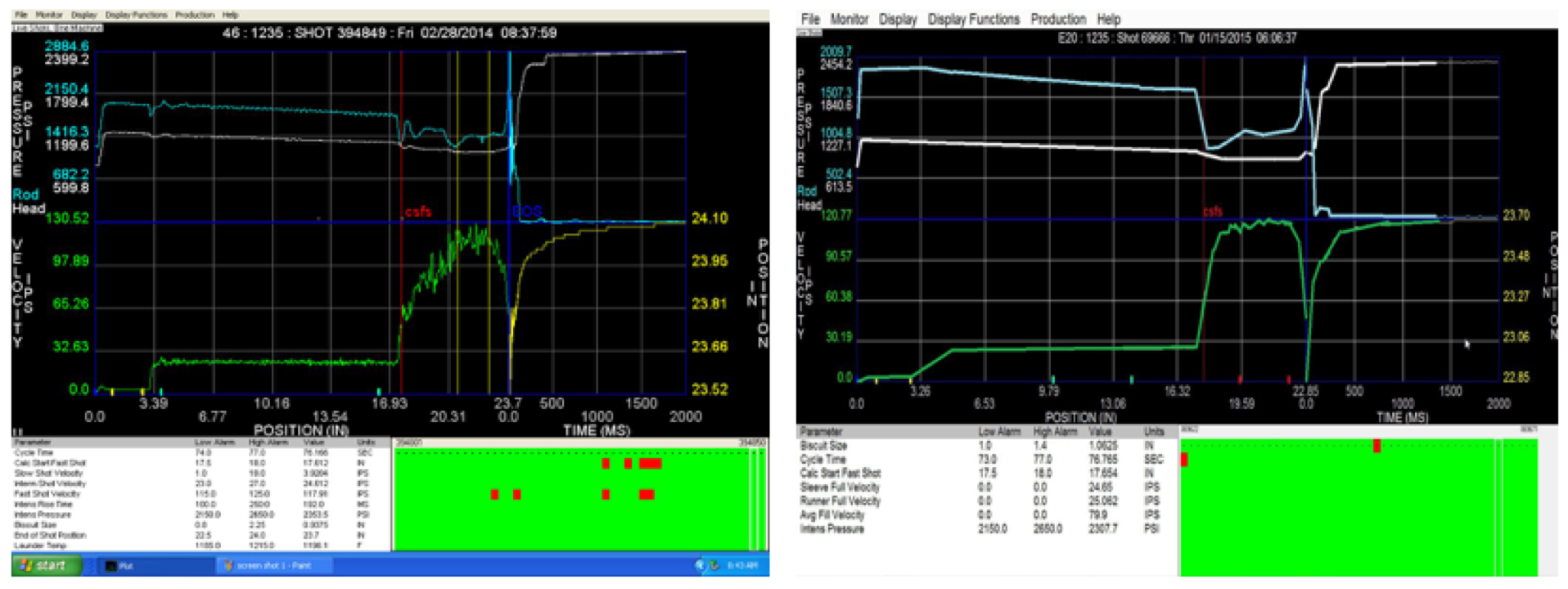
- Rack & Pinion Actuated Rotary Encoders – Many machine builders employ this type of arrangement. It requires mounting a rack assembly in a milled slot in a follower tail rod and then mounting a spring-loaded pinion gear so it turns the shaft of the rotary encoder as the rack passes by during the shot stroke to translate the turns on the encoder to linear position changes. While the encoder is generally reliable in die casting environment, the mechanical connections and slippage or poor fit of the pinion gear to the rack assy. As it passes often at very high speeds, leads to false or inaccurate data. (Fig. 11) Further metal blow back which gets in the rack grooves can result in missed counts.

Fig.11 – Same machine running same part before and after. Left: Rack-and-pinion shows false data and missed counts. Right: Visi-trak sensor is clear and accurate
- Magnetic strip encoders for mounting on follower tail rod – very few known installations in North America. No knowledge of long-term reliability or lack thereof.
- Magneto Restrictive Technology – Temposonics and Baluff are two of leading brand names. “Requires deep hole drilling of clearance for tube that guides the strain pulse generated when magnetic travelling with shot piston passes over excited rod. Works on the Doppler Effect to measure the time to reflect back signal which is proportional to changing stroke. These devices are well suited for slow to average speed applications, and provide excellent position resolutions but have not been used extensively in high speed die casting due to low frequency response and because of need to deep hole clearance which has to penetrate through a sealed hole in the cap end of the shot cylinder where many utilize an adjustable screw arrangement to adjust shot cylinder stroke. Since many machines have an adjustment screw in this area it is impossible to mount the sensor in its preferred position and difficult to mount externally because of alignment issues needed for correct sensor operation.
The Visi-Trak sensor with FasTrak2 board design sets the standard for accurate, high speed sensing and data collection using position-based sampling for the very high-speed filling phase (Fig. 12):

Fig. 12
- Position based sampling = fast, reliable and accurate performance
- All digital system with nothing to calibrate.
- Designed specifically for the harsh die casting environment.
- Proven for over 40 years to be robust combination.
There will be more to come on other elements of Visi-Trak’s building blocks for providing total die casting Process Automation and Controls.


Comments are closed